|
Voltage drop and Headlight output: Decreases lighting output by as much as 20% Near a bulb's working design Voltage, a drop of only a half of a Volt results in a halogen bulb producing much less light. Many bikes have shown a 1 or even 2 Volt drop at the bulb, and I have confirmed this on my own Bikes. And this is also on new or like new Bikes. After installing a relay kit, you will have a drop of ~.1 Volt, That's 1/10th of a Volt in case you miss the decimal. There is always going to be some Voltage drop, This is normal with any switch contact. But this is about the minimum possible. This low Voltage drop is the proof that the system is a good one. All the wiring, connectors, and components are working as they should. Headlight and Starter Switch’s Headlight switches and starter (this is how your headlight turns off when you hit the starter button) switch’s are usually a weak part of a bike's electrical system. Even with a stock 55/60 watt bulb, headlight switches and connectors can break down early in a bike's life. This is because ALL of the electricity that goes to your headlight bulb is passing through those little switch contacts in your handlebar switch units. Note: Some bikes do actually come with headlight relays, but the number is few. Even on newer Bikes. When you are done completing this install, your headlights will function as they did with the dimming while using the starter button, everything is completely plug and play, no cutting or splicing here. After installing the headlight relays, Your switches will now only be controlling the relays, and the current needed to run them is measured in milliamps. So here I decided to clean up some old wiring I had added to a bike over the last couple years, and install one of my pre made wiring kits, so I can get some voltage drop readings at the bulb before and after the relay harness, and photos showing how easy the harness is to install. My wife's bike will be next as I plan to add a 3rd fuse box to her bike, and clean up some wiring there as well. She had a full 2 volt drop at the headlight bulb, that has been reduced to .08 volts.
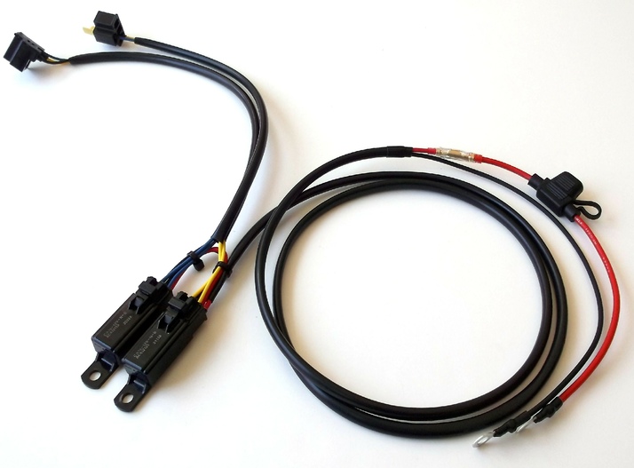
Here I am going to install the relay harness along with some other goodies that we will not be getting into, but they are all built into a single plug and play harness with 4 relays and 2 wires running to a secondary fuse box near the battery. Normally in most cases you will connect the headlight relay harness directly to your battery. ( the rest of the wiring is plug and play for some aux fog lights, done with bullet terminals and pigtails to tap into the factory wiring so no factory wiring need to be cut on this bike, but its a little more complicated. So we will not be discussing it ) Thanks I hope this can provide someone with help in doing it themselves. |
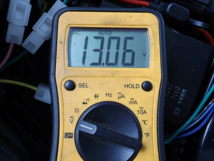 First we will get some voltage readings at the battery with the Bike running at idle.
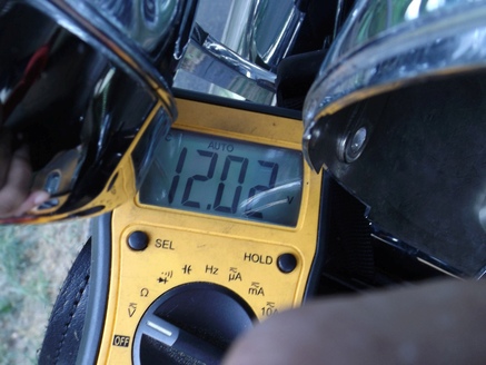 And then the Headlight bulb with the Bike running at idle.
 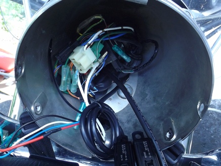 We have a 7 inch headlight housing so there is plenty of room in this for all these
relays I am adding.
We have a 7 inch headlight housing so there is plenty of room in this for all these
relays I am adding.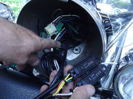 Here you can see the relay's and the single harness that runs through the back of
the headlight housing.
Here you can see the relay's and the single harness that runs through the back of
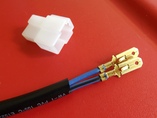
the headlight housing.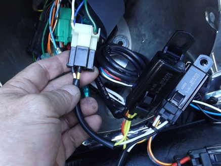 Next we will connect the bikes original H4 bulb connector to the relay harness H4
coupler.
Next we will connect the bikes original H4 bulb connector to the relay harness H4
coupler. 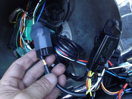 And then cover it with a large piece of shrink tube, as the original connector wiring
is somewhat exposed.
And then cover it with a large piece of shrink tube, as the original connector wiring
is somewhat exposed.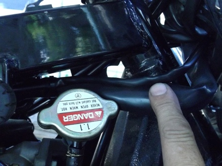 You want to try and make sure you run this with the main harness if possible. and
give yourself plenty of harness to turn from lock to lock without pulling or binding
of the harness.
You want to try and make sure you run this with the main harness if possible. and
give yourself plenty of harness to turn from lock to lock without pulling or binding
of the harness.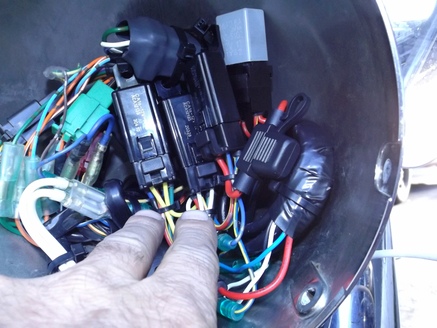 Now we are going to get everything tied up into place and tucked back in the housing
so the headlamp will fit back in properly, You want to secure everything as you don't
want any flexing of the wiring at the relay base, and nothing rattling around. we
can then make the rest of our connections and finish routing the harness to the battery.
Now we are going to get everything tied up into place and tucked back in the housing
so the headlamp will fit back in properly, You want to secure everything as you don't
want any flexing of the wiring at the relay base, and nothing rattling around. we
can then make the rest of our connections and finish routing the harness to the battery.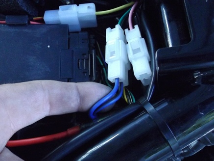 I ran the wiring right down the center of the frame with the main harness on the
bike, Then inserted my terminals in this connector here.
I ran the wiring right down the center of the frame with the main harness on the
bike, Then inserted my terminals in this connector here. 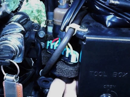 Here is a picture of the secondary fuse box, it lays under the left side cover,
wrapped with a piece of 3M adhesive lined foam to keep it from rattling around.
Here is a picture of the secondary fuse box, it lays under the left side cover,
wrapped with a piece of 3M adhesive lined foam to keep it from rattling around.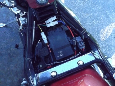 Here is a photo of what we cleaned up, most of the relays in the headlight were
under the seat at one time. Now only the horn relay, main fuse for the secondary
fuse box and some connectors reside under there. Along with another fuse for the
tender cable.
Here is a photo of what we cleaned up, most of the relays in the headlight were
under the seat at one time. Now only the horn relay, main fuse for the secondary
fuse box and some connectors reside under there. Along with another fuse for the
tender cable.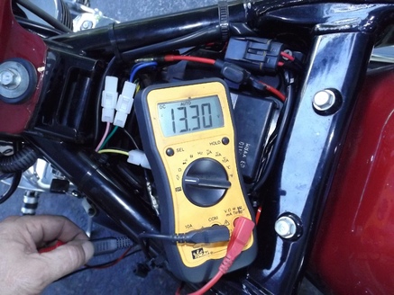 Voltage reading at the battery with the bike idling (this was after a coolant change
as well, so it had been warmed up and idling a little higher this time)
Voltage reading at the battery with the bike idling (this was after a coolant change
as well, so it had been warmed up and idling a little higher this time)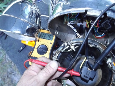 And at the headlight bulb connector idling at idle.